Share
Pin
Tweet
Send
Share
Send
Of course, one could buy it in a store for $ 25-30, but their power was embarrassing. To power even a laptop, a current with 0.5-1 amperes, which most automobile inverters give out, is clearly not enough.
Choice of concept.
By my nature, I am a lazy person, so I decided not to "reinvent the wheel", but to search the Internet for similar designs, and adapt the scheme of one of them for my craft. Time was running out, so the priority was simplicity and the lack of expensive parts.
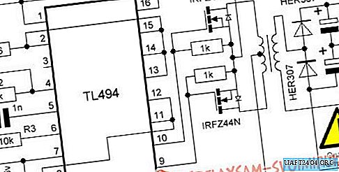
On one of the forums, a simple circuit was chosen on the common PWM controller TL494. The disadvantage of this circuit is that it receives a rectangular voltage of 220 V at the output, but this is not critical for switching power supply circuits.
Selection of parts.
The circuit was chosen because almost all the details could be taken from a computer power supply. For me it was very critical, because the nearest specialized store is more than 150 km away.

Output capacitors, resistors, and the microcircuit itself were soldered from a pair of faulty power supplies at 250 and 350 W.
The difficulty arose only with high-frequency diodes for converting the voltage at the output of the step-up transformer, but here old stocks saved me. Characteristics KD2999V I was quite satisfied.
Assembly of the finished device.
I had to assemble the device within a couple of hours after work, because a long trip was planned.
Since time was very limited, I simply did not look for additional materials and tools. I used only what was at hand. Again, because of speed, I did not use the samples of printed circuit boards provided on the forums. In 30 minutes, a printed circuit board was developed on a piece of paper, and its drawing was transferred to textolite.
Using a scalpel, one of the foil layers was removed. On the remaining layer, deep grooves were drawn along the lines drawn. Using curved tweezers, it turned out to be the most convenient, the grooves were deepened to a layer of a non-conductive current. In places where parts were installed with an awl, it didn’t get on the photo, holes were made.

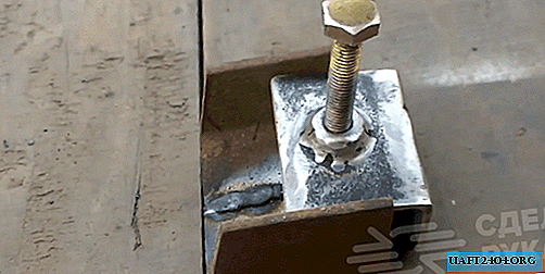
I started the assembly with the installation of a transformer, used to lower one of the blocks, it was simply turned over and instead of lowering the voltage from 400 V to 12 V, it increased it from 12 V to 268 V. By replacing the resistors R3 and capacitor C1, it was possible to reduce the output voltage to 220 V, but further experiments showed that this should not be done.
After the transformer, in order to reduce the size, I installed the remaining parts.


Field-effect transistors, it was decided to put on elongated inputs, so that they are easier to attach to the cooling radiator.

As a result, we got such a device:

Only the finishing touch remains - the radiator mount. There are 4 holes on the board, although there are only 3 self-tapping screws, it was just that during the assembly process, it was decided to slightly change the position of the radiator for a better appearance. After the final build, this is what happened:
Tests
There was no time to specifically test the device, it was simply connected to the battery from an uninterruptible power supply unit. The output was connected to a load in the form of a 30 W bulb. After it caught fire, the device was simply abandoned in a backpack, and I went on a business trip for 2 weeks.
For 2 weeks, the device has never failed. Various devices were powered from it. When measured with a multimeter, the maximum current obtained reached 2.7 A.
Share
Pin
Tweet
Send
Share
Send