Share
Pin
Tweet
Send
Share
Send
To eliminate this negative phenomenon, there is a not very complicated circuit on the integrated power regulator, which was developed back in the Soviet Union, but so far it is not difficult to buy on the Internet. Price from 40 rubles and above. It is called KP1182PM1. Works well in various regulatory devices. But we will build a softstarter.

Soft starter circuit diagram
Now consider the circuit itself.

As you can see, the components are not very many and they are not expensive.
Will need
- Microcircuit - КР1182ПМ1.
- R1 - 470 ohms. R2 - 68 kilo-ohms.
- C1 and C2 - 1 microfarad - 10 volts.
- C3 - 47 microfarads - 10 volts.
Development board for mounting circuit components "so as not to bother with the manufacture of the printed circuit board."
The power of the device depends on the brand of triac that you put.
For example, the average value of the current in the open state for different triacs:
- BT139-600 - 16 amps,
- BT138-800 - 12 amps,
- BTA41-600 - 41 amp.
Device assembly
You can put any others that you have and which suit you in terms of power, but you need to consider that the more powerful the triac, the less it will heat up, which means it will work longer. Depending on the load, you need to use a cooling radiator for the triac.
I installed the BTA41-600, you can not install a radiator for it at all, it is powerful enough and will not heat up during repeated and short-term operation, under a load of up to two kilowatts. I simply do not have a more powerful tool. If you plan to connect a more powerful load, then think about cooling.
Assemble the parts for mounting the device.

We also need a "closed" outlet and a power cable with a plug.

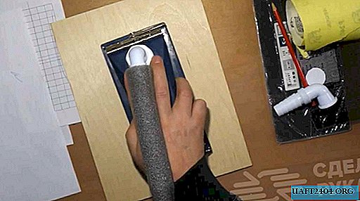
It’s good to size the prototype board using large scissors. It is cut easily, simply and accurately.

We place the components on the breadboard. For a microcircuit, it is better to solder a special socket, it costs a penny, but it greatly facilitates the work. There is no risk that you overheat the legs of the microcircuit, you do not need to be afraid of static electricity, and even if the microcircuit burns, you can replace it in a couple of seconds. It is enough to take out the burnt and insert the whole.

The parts are immediately soldered.

We place new parts on the board, referring to the diagram.

Gently solder.

For the triac nests need to be slightly drilled.

And so in order.

We insert and solder the jumper and other details.

We solder.

We check the compliance with the circuit and insert the microcircuit into the socket, not forgetting the key.
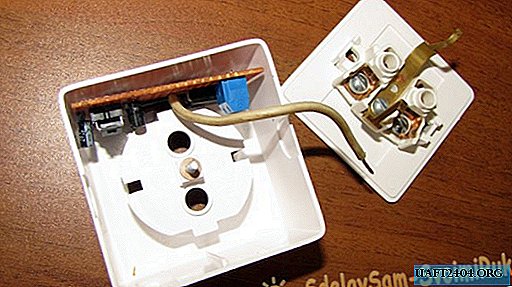
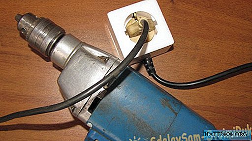
We insert the finished circuit into the outlet.

We connect power to the outlet and circuit.

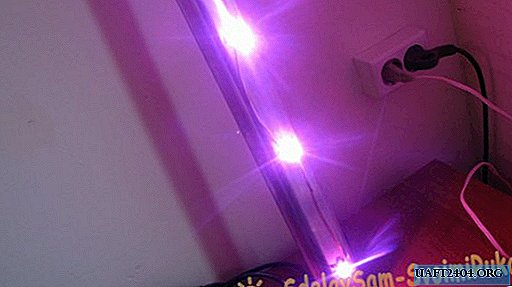
Work check
Check the device in operation.
Caution! All elements of the circuit are under a direct voltage of 220 volts! Life threatening!
We finally assemble the device.


We carry out the last performance check.
In order not to confuse this device with a simple extension cord, it must be marked in any way. I did this with a self-adhesive price tag and tape.

Please see the video test of this device. The change in the behavior of the device at startup is clearly shown.
Good luck in your affairs and concerns.
Watch the video of the device
Share
Pin
Tweet
Send
Share
Send