Share
Pin
Tweet
Send
Share
Send
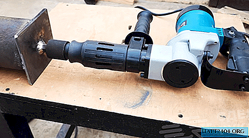
Washing machines often fail, while maintaining the full efficiency of their engine. Its power and actual speed are well suited for the use of this spare part in the manufacture of home-made machines. As it turned out, such an electric drive is also an ideal solution for installation on a makeshift grinder.

Materials used
It took not so much to make:
- motor from the machine;
- its native starting capacitor;
- part of sheet sheathing machine;
- 4 rubber feet from the washer;
- plywood sheet;
- a piece of 5 cm thick-walled tube with an inner diameter of 14 mm;
- 2 identical bearings;
- glass sealant;
- sheet metal with a cross section of 8 mm;
- corner 63x63 mm;
- profile pipe 40x40 mm;
- profile pipe 30x30 mm;
- elongated nut;
- steel strip with a cross section of 10 mm;
- furniture gas shock absorber;
- power button;
- plastic plugs 30x30 and 40x40 mm;
- bolts and nuts M12, M10, M6 and M5.
The main detail of the whole structure:


The process of manufacturing the grinder from the washing machine engine
For starters, I made the tension rollers.

This is a factory metal. Ours will be homemade, wooden. Moisture-resistant plywood is suitable for their manufacture, its thickness is not so important.

From it you need to make pancakes, which are then glued into a roller. First, I install a drill bit on a tree with a diameter of 102 mm. I cut 9 plywood pancakes for the lead roller. The number of circles depends on the thickness of the existing plywood and the width of the tape, which will then be used.

Now you need to glue the pancakes. First you have to grind them a bit to remove chips from the crown. I lubricate the side of the circles with PVA glue and form a wide multi-layer roller. For normal gluing, I fix the workpiece under the press.

While the drive roller is dry, you can make a driven roller. A 64 mm crown is used for it. Again, using a drill, I cut out 9 pancakes from the same plywood and glue under the press.

To prevent stratification of the rollers after they dry, I made 2 side holes in them and additionally pulled a pair of screws on each side.
I carry out balancing of the rollers in the lathe, a little grinding off irregularities and achieving smoothness of the workpieces.

To fix the drive roller on the engine shaft, you need to make an adapter. For this, a piece of a thick-walled tube is used.

In most cases, a pipe with an internal diameter of 14 mm will be required. To tighten the tube on the shaft of the electric motor, I drill a hole and cut the M5 thread. At the second end of the tube, I weld an M12 bolt.


I expanded the hole of the driving roller to fit the tube to half the depth. The rest of the narrow part will include the thread from the M12 bolt.
In the driven roller you need to put a pair of bearings, one on each side. Their size is not so important, you can use any, most important, to a suitable inner diameter. I am preparing landing seats for bearings on a lathe.


To make the surface of the rollers smoother, I decided to cover them with glass glue. To do this, I fix them alternately in the lathe, and evenly smear around the perimeter and ends.


Now you need to make a frame for installing an electric motor. As a basis I use a metal sheet with a cross section of 8 mm. I cut a rectangle with sides 220 to 310 mm.

For direct engine mounting, you will need 2 corners. I am preparing lengths of 130 mm. Under the electric motor, the 63rd corner was ideally suited.

I lay the steel plate on a flat surface, put the corner and the engine, after I make the markings for drilling mounting holes with a 6 mm drill.

So that in the future the corner does not interfere with the fixing bolt of the drive roller, you need to select metal near the shaft. The easiest way is to cut out a small triangle.


I mount the corners on an electric motor using four M6 nuts with a press washer.

I install the motor with mounts in place, make markings and weld the corners to the sole of the machine.

I cut a blank 300 mm long from a 40x40 profile pipe. I make another segment of the same length, but already from a profile pipe 30x30 mm.

Now you need to make a tape adjustment mechanism. To get started, take an elongated nut and turning its edges.

I weld it to a steel strip with a cross section of 10 mm. I drill a hole in the strip and cut the M10 thread for the bolt on which the driven roller will be fixed.

Then from a previously cut square pipe 30x30 welded a L-shaped workpiece. I welded nuts to fix the strip made. He also fixed a nut with a bolt on the perpendicular wall of the square opposite the cap of the bolt, on which the driven roller will be mounted. By twisting or unscrewing a short bolt, it will be possible to change the angle of the roller, thereby setting up the machine.


I put a 40x40 profile pipe vertically on the machine platform and weld it. At the same time, I try on the spot so that the driven roller is opposite the leader, which in turn is mounted on the motor shaft.

To ensure a smooth tension of the tape, it is necessary to install a gas furniture shock absorber between the vertical pipe 40x40 and the L-shaped holder of the roller 30x30.


I make the support platform for the machine from the available materials. Using a small section of the profile pipe 40x40 and 63rd corner. I made a cutout on the pipe to increase the weld area. The corner was attached with bolts, since it will need to be removed during maintenance. I did all the blanks without preliminary size, just fitting them in place.


And now I am preparing a table for the emphasis of the machined workpieces. To do this, I use the same sheet metal with a cross section of 8 mm. The width of the table was 80 mm.
I’m preparing the base for the table. To do this, take a pipe 40x40 120mm long. I drill a hole in it, I hone the end face in a semicircle and cut the M10 thread. Making small sheet metal ears. They will act as loops. I weld the ears to the countertop.


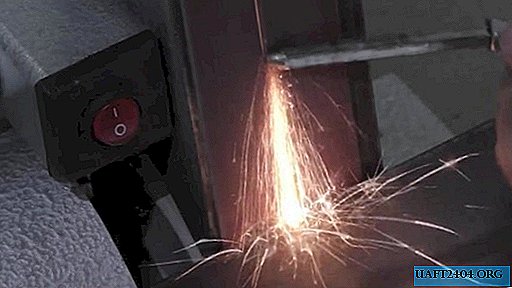
Now I cut the threads in the sole of the machine under 4 soft rubber legs to minimize vibration. They can be dismantled from a broken washing machine. Immediately I cut off a blank from its body for the manufacture of a protective casing. I cut a 130 mm wide strip along the entire length, then shorten it in place.

In a vice using a hammer, wooden blocks and other devices, the strip must be bent, and drilling holes in it to get a full protective casing. All details are ready.

Having at the disposal of all the necessary parts I paint the elements of the machine.


It’s time to build. Everything is going as a constructor. You’ll have to tinker a bit with the button, capacitor and solder wires. I was even able to find 2 plastic plugs under the 30x30 pipe and one under 40x40, so everything looks good.


As shown by verification, engine power is enough for the full operation of the machine. Thanks to the use of a gas shock absorber, it is possible to mount emery tape of various lengths on the rollers, thereby having the opportunity to use factory consumables, rather than glue the sanding tape yourself.


Share
Pin
Tweet
Send
Share
Send